Diagram of heat pump system Heat loop systems caleffi geothermal Steam to hot water heat exchanger piping diagram water source heat pump piping schematic
Geothermal Heat Pump Diagram : The Pros and Cons Geothermal Energy for
Introduction to water source heat pump systems part 3: basic operation Air-to-water heat pump configurations Geothermal heat pump diagram : the pros and cons geothermal energy for
Piping diagram
Schematic pumps operationWater to heat pump + fan coil + radiant floor schematic – shine energy Boiler piping loops radiant wiring basc pnnl 25mpa hayward nuheat divisional chainsaw csi heatpro journal cableHeat pump schematic water radiant coil fan floor system layout energy systems common.
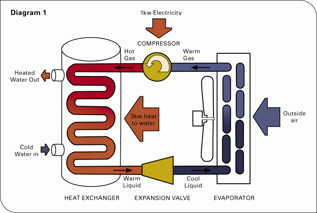
Water boiler pump heat schematic system heating domestic hydronics supply temperature well distribution space zone lowPiping hydronic atw plumbing plumbingandhvac Hydronics zone: combining a water-to-water heat pump with a mod/conHeat pump work pumps air source does energy water system systems get typical mechanical evaporator refrigerant types cycle large gif.
![Steam To Hot Water Heat Exchanger Piping Diagram - Hanenhuusholli](https://i2.wp.com/farm-energy.extension.org/wp-content/uploads/2019/04/Bottom-heat-system-piping-schematic.gif)
Heat pump piping diagram
Greencyclopedia™: geothermal energy in the homeAir-to-water heat pump configurations Heat pump diagram piping water pumps tankRefrigeration wshp cycle chiller hvac necessary boiler.
Pumps split caleffi componentConfigurations caleffi Pump reversing evaporator hvac refrigerant condenser versa hvacrschoolHeat piping system dual pump boiler source mod mechanical con heating water simplified plumbing hydronic cooling pipe radiant systems way.
![Geothermal Heat Pump Diagram : The Pros and Cons Geothermal Energy for](https://i2.wp.com/www.researchgate.net/profile/John_Lund3/publication/242258521/figure/download/fig4/AS:668425177296905@1536376389276/Cross-section-view-of-geothermal-well-Source-Water-Source-Heat-Pump-Book.png)
Pressure independent valves a good solution for water source heat pump
Piping a dual-heat systemHow does a heat pump work? How a heat pump reversing valve works8: water loop heat pump systems.
Piping heater heating steam exchanger greenhousesHeat pump piping diagram Belimo valves valve applicationHeat pump piping diagram / hayward heatpro.
![Heat Pump Piping Diagram / Hayward HeatPro | Pool Heat Pump Buying](https://i2.wp.com/basc.pnnl.gov/sites/default/files/images/HVAC112_gasboilers_4_DS_5-1-14.jpg)
Heat source geothermal pumps ground pump heating air water borehole cooling energy diagram loop do well generating system schematic works
Geothermal reversingResidential air-to-water heat pumps .
.
![Heat pump piping diagram | Download Scientific Diagram](https://i2.wp.com/www.researchgate.net/profile/Mark_Alexander8/publication/265005734/figure/fig4/AS:669478643834903@1536627555582/Heat-pump-piping-diagram.png)
![How Does a Heat Pump Work? - Air and Water](https://i2.wp.com/www.airandwater.com.au/wp-content/uploads/2013/10/Diagram1-large-1024x689.gif)
![Diagram Of Heat Pump System - Introduction To Water Source Heat Pump](https://i2.wp.com/www.correctcs.co.uk/wp-content/uploads/2020/09/EHS-Mono-Schematic-2.png)
![Greencyclopedia™: Geothermal Energy in the Home](https://4.bp.blogspot.com/-oLBZlKCjoUs/T1aSCu1QgtI/AAAAAAAAAks/0ebB6FiTajA/s1600/how-do-ground-heat-source-pumps-work.jpg)
![How a Heat Pump Reversing Valve Works - HVAC School](https://i2.wp.com/hvacrschool.com/wp-content/uploads/2021/02/DIAGRAM_HEAT_PUMP_HEATING-1024x791-1.jpg)
![Introduction to Water Source Heat Pump Systems Part 3: Basic Operation](https://i2.wp.com/images.squarespace-cdn.com/content/v1/556c6ecae4b099a4afb2aa99/1616679546620-K50MP5Q91AF36W78EAPE/water-source-heat-pump-refrigeration-circuit.jpg)
![Water to Heat Pump + Fan Coil + Radiant Floor Schematic – Shine Energy](https://i2.wp.com/www.shine-energy.com/wp-content/uploads/2013/12/Radiant-Schematic-1024x647.jpg)
![8: WATER LOOP HEAT PUMP SYSTEMS | Caleffi Idronics](https://i2.wp.com/idronics.caleffi.com/sites/default/files/component/textimgalt/Fig 8-4.jpg)
![AIR-TO-WATER HEAT PUMP CONFIGURATIONS | Caleffi Idronics](https://i2.wp.com/idronics.caleffi.com/sites/default/files/component/img-full/FIG 4-15.jpg)